Creating Site-to-site WireGuard connections in MikroTik
This guide walks through building a MikroTik WireGuard site-to-site VPN between two RouterOS 7 devices, whether that's two physical routers, two CHR instances such as the ones we host at BGOcloud, or a mix of both. You'll set up the WireGuard interfaces, configure a standard two-fixed-site tunnel, handle the NAT (road warrior) case where one router can't be dialed directly, and route an entire site's traffic through the tunnel instead of just a couple of subnets.
For each tunnel you set up, use a separate WireGuard interface and at least a /30 subnet. You'll need access to both routers while configuring this.
Table of Contents
1a. Create the WireGuard Interface
On both routers, open WireGuard and click New. Name the interface whatever makes sense (to-site-2 is fine) and set a listening port if you want a specific one rather than a random default. Apply, then note the listening port and the public key on both sides. You'll need them in a minute.
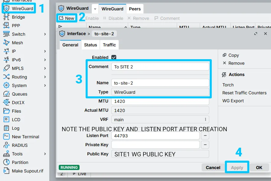
interface wireguard print #to note the public key and port
1b. Allow the WireGuard Port Through the Firewall
If you've locked down the input chain the way our security basics article covers, you'll need an explicit rule to let the handshake through. MikroTik's own default is to accept everything except invalid connections, so this only matters if you've tightened input yourself. Under IP > Firewall, add:
- Chain: input
- Protocol: UDP
- Destination port: the WireGuard port you set above
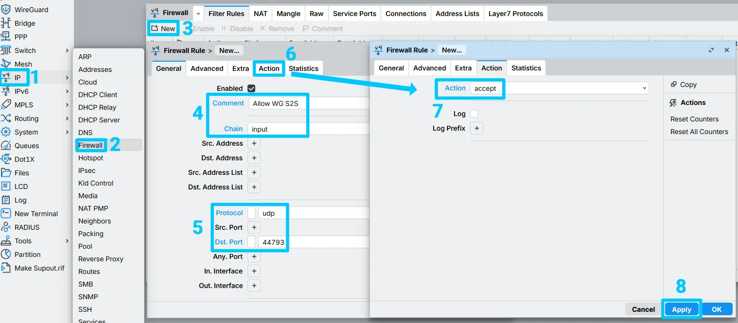
You can tighten this further by matching the remote router's public IP as a source address, if it's static.
1c. Assign a Tunnel IP Address
Under IP > Addresses, add an address from your chosen /30 to the new interface. These examples use 10.5.0.0/30.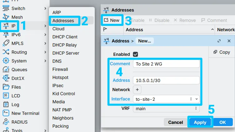
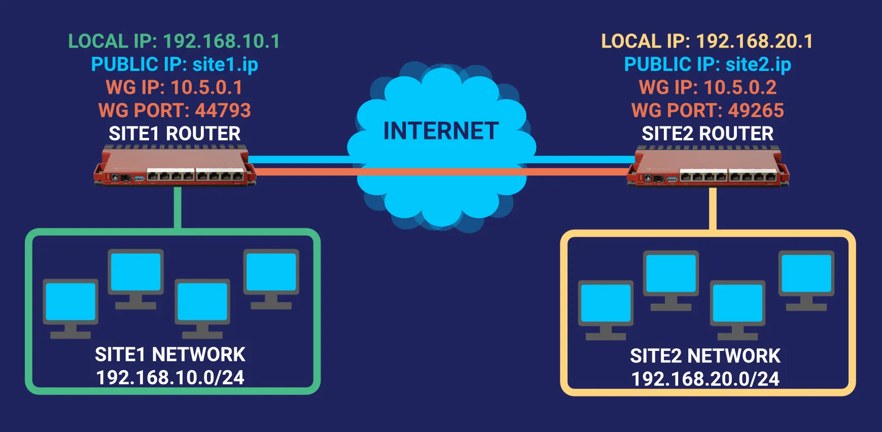
The network below is what we're building. Swap site1.ip and site2.ip for your actual public IPs, and add more subnets to the allowed-address lists if you need to route more than one network per side.
Head to WireGuard > Peers and click New.
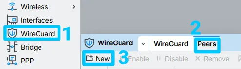
Unlike a typical WireGuard setup for a phone or laptop, there's no separate client config to generate here. Each router's peer entry just points straight at the other router.
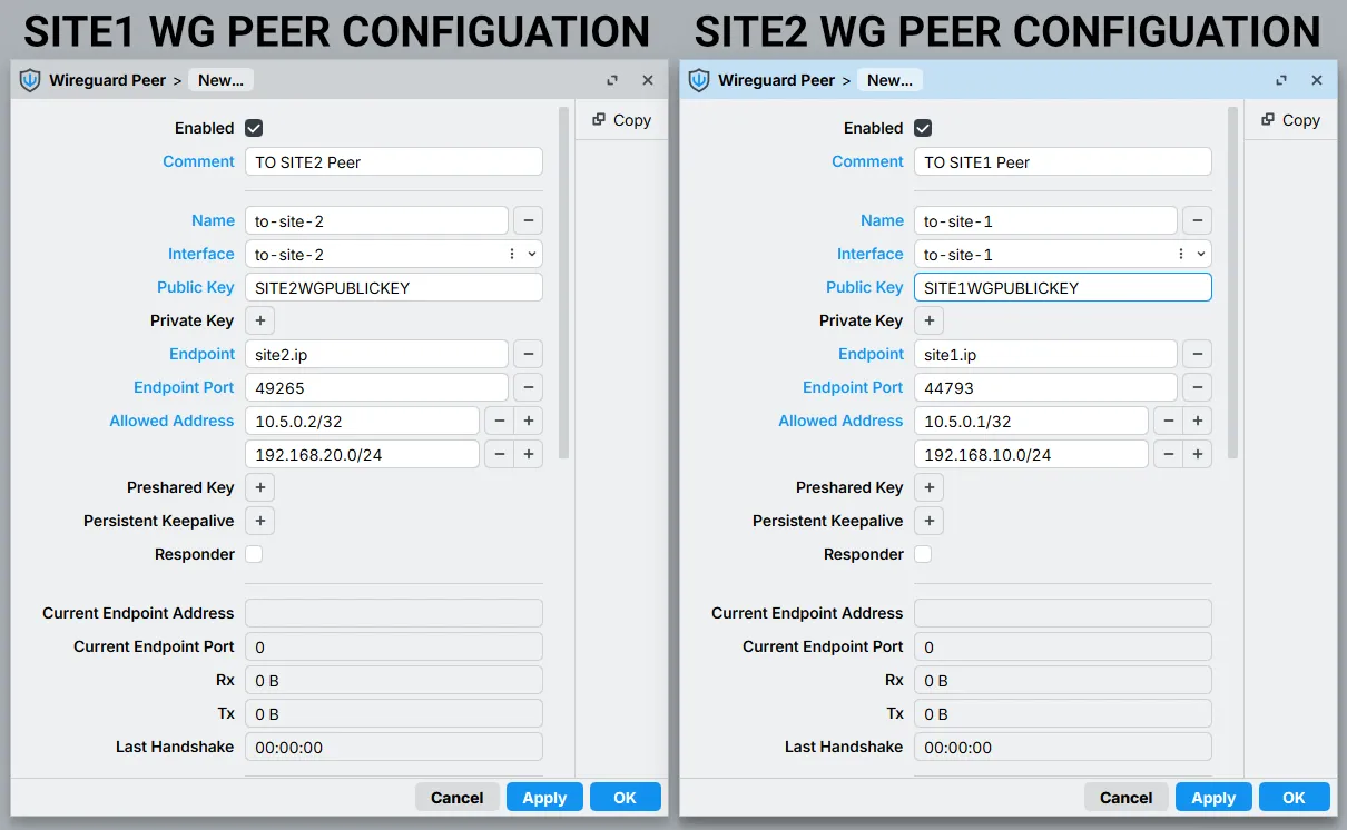
2a. Configure the SITE1 Peer
- Name: To-Site-2
- Interface: to-site-2 (the SITE1 WireGuard interface)
- Public key: SITE2's WireGuard interface public key
- Endpoint: site2.ip (SITE2's public address)
- Endpoint port: SITE2's WireGuard port (e.g. 49265)
- Allowed addresses: SITE2's WG interface address (10.5.0.2/32) plus the SITE2 subnet you want reachable (192.168.20.0/24)
2b. Configure the SITE2 Peer
- Name: To-Site-1
- Interface: to-site-1 (the SITE2 WireGuard interface)
- Public key: SITE1's WireGuard interface public key
- Endpoint: site1.ip (SITE1's public address)
- Endpoint port: SITE1's WireGuard port (e.g. 44793)
- Allowed addresses: SITE1's WG interface address (10.5.0.1/32) plus the SITE1 subnet you want reachable (192.168.10.0/24)
interface wireguard peer add name="to-site-2" comment="TO SITE2 PEER" interface=to-site-2 \
public-key=<SITE2 WG interface public key> endpoint-address=<SITE2 IP> endpoint-port=49265 \
allowed-address=10.5.0.2/32,192.168.20.0/24
#SITE2
interface wireguard peer add name="to-site-1" comment="TO SITE1 PEER" interface=to-site-1 \
public-key=<SITE1 WG interface public key> endpoint-address=<SITE1 IP> endpoint-port=44793 \
allowed-address=10.5.0.1/32,192.168.10.0/24
Check both sides: a successful ping between the two tunnel addresses (10.5.0.1 and 10.5.0.2) confirms the handshake is live. If ICMP is blocked somewhere along the path, the traffic counters and handshake timer on the peer entry tell you the same thing.
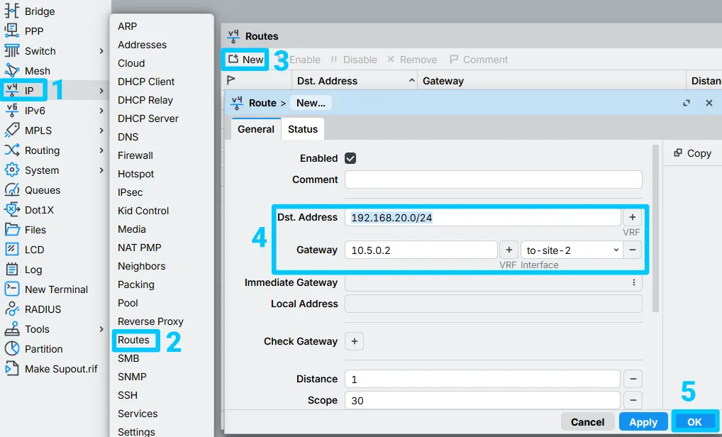
2c. Add the Routes Between Sites (for partial redirect)
Last piece for a basic S2S setup: each router needs a route pointing the other site's subnet at the tunnel.
- Route in SITE1 for SITE2: Destination 192.168.20.0/24, gateway 10.5.0.2 via to-site-2
- Route in SITE2 for SITE1: Destination 192.168.10.0/24, gateway 10.5.0.1 via to-site-1
ip route add dst-address=192.168.20.0/24 gateway=10.5.0.2%to-site-2
#On Site2
ip route add dst-address=192.168.10.0/24 gateway=10.5.0.1%to-site-1
#gateway is written as <ip address>%<interface>
A road warrior, in this context, is any endpoint that can't be dialed directly: a home router behind an ISP NAT, a hotel network, a travel router, or an LTE-connected device whose IP changes on its own. The S2S setup above assumes both sides have a fixed, reachable address. This section is for when one side doesn't.
We'll connect a physical MikroTik device at a home or remote site to a CHR. Swap yourmchr.ip for your CHR's actual public IP.
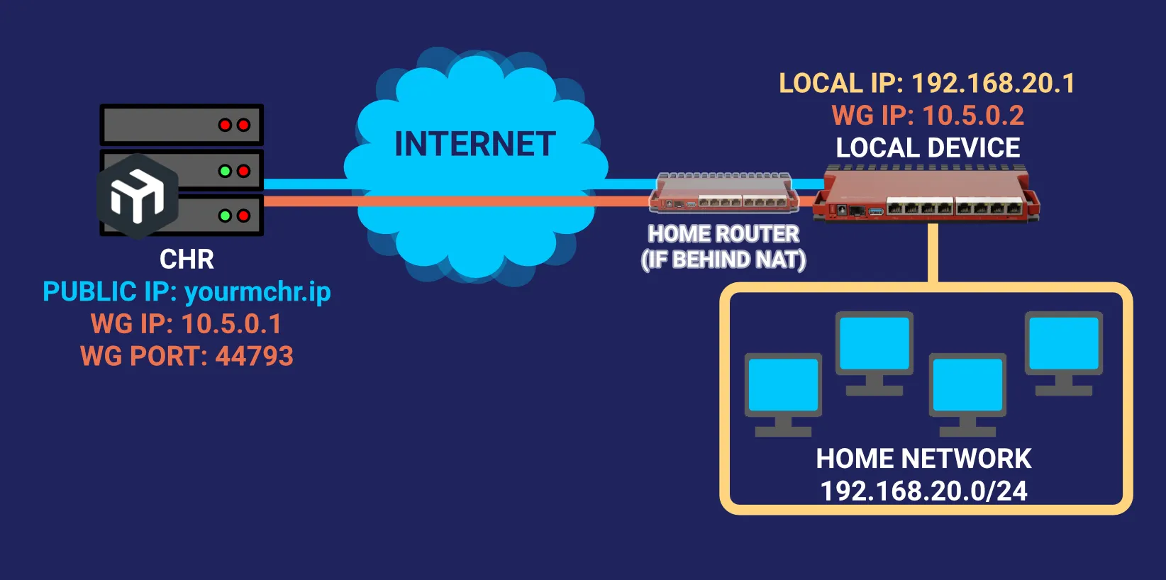
Same starting point as before: WireGuard > Peers > New.
The difference this time: the CHR's peer entry only ever gets the local router's public key and its local subnet. It never gets an endpoint address, because there isn't a reliable one to give it.
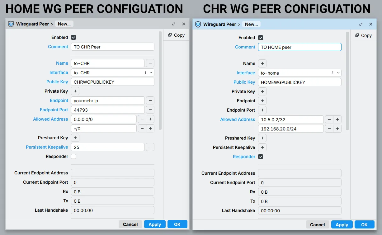
3a. Configure the Local Router Peer
- Name: To-CHR
- Interface: to-chr (the local router's WireGuard interface)
- Public key: CHR's WireGuard interface public key
- Endpoint: yourmchr.ip (the CHR's public address)
- Endpoint port: CHR's WireGuard port (e.g. 44793)
- Allowed addresses: 0.0.0.0/0 and ::/0 for a full tunnel, or just the CHR's tunnel IP (10.5.0.1/32) plus specific remote subnets if you don't want everything routed
- Persistent Keepalive: 25 seconds or lower. This is what keeps the NAT mapping open.
3b. Configure the CHR Peer (Responder)
- Name: To-Home
- Interface: to-home (the CHR's WireGuard interface)
- Public key: local router's WireGuard interface public key
- Allowed addresses: the local router's tunnel address (10.5.0.2/32) plus whatever home subnet should be reachable (192.168.20.0/24)
- Responder: checked/true. This stops the CHR from wasting cycles (and log lines) trying to dial an address it can't reach. The local router is always the one that initiates.
interface wireguard peer add name="to-chr" comment="TO CHR PEER" interface=to-chr \
public-key=<CHR WG interface public key> endpoint-address=<your CHR IP> endpoint-port=44793 \
allowed-address=0.0.0.0/0,::/0 persistent-keepalive=25
#On the CHR
interface wireguard peer add name="to-home" comment="TO HOME PEER" interface=to-home \
public-key=<home router WG interface public key> \
allowed-address=10.5.0.2/32,192.168.20.0/24 responder=yes
Same verification as before: ping between 10.5.0.1 and 10.5.0.2, and check the handshake timer on both peers.
3c. Add the Routes Between Sites (for partial redirect)
In the above example, our CHR does not have a local network and all the traffic is allowed to it, which is intended for a full traffic redirect. But If you plan to use the Road Warrior setup for an ordinary site-to-site connection, e.g. docker apps in the CHR, or for mobile routers with access to the work resources, you may add routes in both devices. In this example, we will take the 192.168.10.0/24 network as the local server/CHR network. Everything is done via IP>Routes.
- Route in CHR/Server for home router: Destination 192.168.20.0/24, gateway 10.5.0.2 via to-home
- Route in home router for CHR/Server: Destination 192.168.10.0/24, gateway 10.5.0.1 via to-CHR
ip route add dst-address=192.168.20.0/24 gateway=10.5.0.2%to-home
#On home router
ip route add dst-address=192.168.10.0/24 gateway=10.5.0.1%to-CHR
#gateway is written as <ip address>%<interface>
Full-tunnel routing needs the allowed-address lists set correctly first: the home side gets 0.0.0.0/0 and ::/0 (done above), and the CHR gets the home network specifically.
The obvious way to do this: add a specific host route to the CHR's IP via your normal gateway, then make the WireGuard interface your default route at a lower distance than your ISP's dynamic default.
That works fine on a router sitting on a fixed network. It falls apart the moment your road warrior device moves, because the "normal gateway" it's routing through changes on every network it joins, and a static route pointing at last week's hotel WiFi gateway is worthless on this week's. Skip this approach for anything mobile.
The fix that actually holds up when the device roams: a separate routing table plus a mangle rule, so the router's own traffic (DHCP renewals, the WireGuard handshake itself) keeps using whatever gateway is currently live, while only LAN client traffic gets pushed into the tunnel.
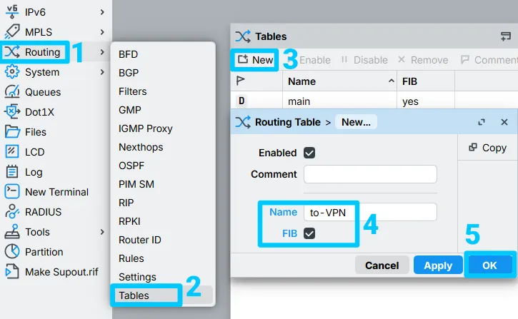
4a. Create the Routing Table
Routing > Tables > New: name it, and enable FIB.
4b. Add the Full-Tunnel Default Route
Add the default route for that table, pointed at the CHR's tunnel address:
- Destination address: 0.0.0.0/0
- Gateway: 10.5.0.1 via to-chr
- Check Gateway: leave unset for a kill switch (no valid route means no traffic if the tunnel drops), or set to ping if you'd rather the router fail open to its normal internet connection when the tunnel's down
- Routing table: to-VPN
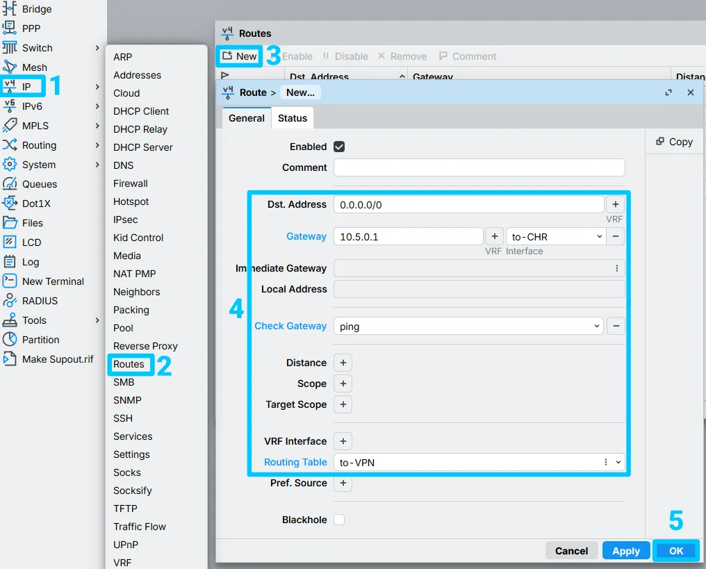
ip route add dst-address=0.0.0.0/0 gateway=10.5.0.1%to-chr routing-table=to-VPN check-gateway=ping
4c. Add the Return Route on the CHR
On the CHR, add the return route so it knows how to reach the home subnet:
- Destination Address: 192.168.20.0/24
- Gateway: 10.5.0.2 via to-home
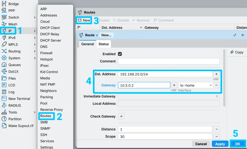
ip route add dst-address=192.168.20.0/24 gateway=10.5.0.2%to-home
4d. Mark LAN Traffic With a Mangle Rule
Last piece: the mangle rule that actually sends LAN traffic into the new table. IP > Firewall > Mangle:
- Chain: prerouting
- Source Address: 192.168.20.0/24
- Action: mark routing
- New routing mark: to-VPN
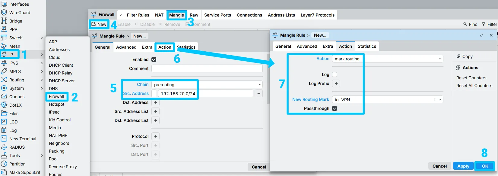
At this point, everything from the home network should be leaving through the CHR. Confirm with an IP checker from a LAN client.
fasttrack-connection rule, or don't rely on FastTrack for anything routed into the VPN.Connect more devices to the WireGuard VPN server, or check more tips for this protocol and the CHR:
Need a MikroTik CHR to run this on? BGOCloud's MikroTik VPS plans give you a fully licensed RouterOS v7 instance with root access, SSD storage, and unlimited traffic options — deployed in under a minute. Everything in this guide works out of the box on our CHR instances, with no extra configuration needed on our end.
You can also browse our full MikroTik CHR knowledge base for more guides on getting the most out of your router.